ШШУХЙиМќзжЃК
Methods for Calibrating Gain Error in Data-Converter Systems
Abstract: All data-converter systems require a voltage reference. High-accuracy systems suffer from many sources of error, with system gain error among the most important. This gain error can be calibrated out with several methods. Digital calibration is common, but introduces errors, which can be compensated with an increase in resolution. Calibration can also be done by trimming the voltage reference, a method that does not introduce errors. This applications note describes how a voltage reference can be trimmed using a digital potentiometer.
A commonly asked training question is: at what resolution would you expect to use a discrete voltage reference in a data-converter system? Novice answers usually suggest the 10-/12-bit region. Well perhaps, but this is a trick question. The real answer is that resolution and accuracy are separate entities. The correct, best answer is understandable in general terms: a high-resolution data converter will be more accurate than a low-resolution data converter. But, there is still more to the answer. A system using low resolution can be made highly accurate with an accurate reference, calibration, or both.
Many factors affect the accuracy of a data-converter system, with gain error among the most important. Gain error is defined as the deviation from ideal at maximum code, ignoring offset error as shown below in Figure 1 for a DAC. ADCs are defined in the same way.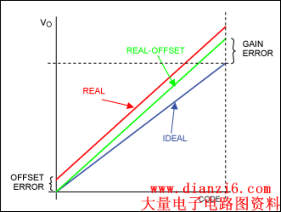
Figure 1. Gain and offset errors.
Gain error is caused by nonideal gain in the analog signal chain and errors in the voltage reference. The error can be calibrated out digitally. However, the digital approach requires the system to use a higher-resolution converter, which can easily increase cost.
This digital method is demonstrated below using an exaggerated example. The system is modeled using an ideal DAC and a nonideal analog output amplifier (Figure 2). To make things simple, assume that the DAC has only 4-bit resolution.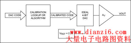
Figure 2. System to demonstrate digital gain calibration.
First consider the ideal situation where the system's gain error is zero, AV = 1. As the DAC input code increases, the output voltage increases accordingly to 2.5V (VREF = 2.5V). Now we make the situation more real, although exaggerated. The gain, AV, is 1.1 (gain error = 10%). The output voltage increases as before, but at code 15. Now VOUT = 2.75V. We can calibrate the system digitally by modifying the DAC code with a lookup table, or by implementing an algorithm in the digital domain. To correct a gain of 1.1 back to an overall gain of 1.0, multiply the code by 1/1.1 = 0.909 (Figure 3). The characteristics of the ideal uncalibrated and calibrated real systems are also plotted.
Figure 3. A digitally calibrated DAC system.
Figure 3 shows an ideal DAC characteristic and an uncalibrated characteristic where the gain error is +10%. By modifying the DAC code, the +10% gain error can be calibrated out. However, this approach introduces a problem that is easily seen by looking at calibrated codes and the differential nonlinearity. Initially, the DAC code increases as normal. However, there is a constant positive DNL. The INL increases until 0.5 LSB INL where the calibrated code does not increase from input code 5 to 6. Taking this further, it can be shown that whatever the calibration required, INL will build up to 0.5 LSB before being corrected back 1 LSB. DNL will at some points be + or - 1 LSB. The only way around this is to increase the DAC's resolution.
Digitally calibrating gain error in this way is quite valid and, in fact, Maxim uses this technique in several devices including the MAX5774. The MAX5774 is a 32-channel, 16-bit DAC and a complex device. This part family contains a multiplier and an adder so both gain and offset errors can be calibrated out.
There is a major advantage of calibration with this digital method: calibration can easily be done using ATE. Some, however, view this as a disadvantage, since it does require the use of ATE. Construction and programming of a lookup table or calibration coefficients manually can be done, but it is time consuming and of little value in a practical production situation.
Another way to calibrate out gain error is to adjust the voltage reference. This method is particularly suited for systems requiring high accuracy but not necessarily high resolution.
The key to this approach is to use a trimmable reference like the MAX6143. This reference has an initial untrimmed accuracy of 0.04% and a temperature coefficient of 3ppm over -40ЁуC to +125ЁуC. Other trimmable references are shown in Table 1 below.
The MAX6143 can be adjusted by simply adding a potentiometer between output, ground, and the trim pin (Figure 4).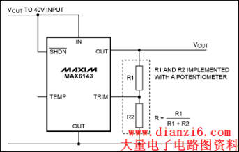
Figure 4. Typical operating schematic for the MAX6143.
The MAX6143's output voltage can be trimmed according to the following equation:
Where:
Therefore, at the extremes, R = 0 and R = 1. With R = 0, VOUT = VNOM ЁС 1.06. With R = 1, VOUT = VNOM ЁС 0.946.
This method of gain calibration can be implemented in two ways: with a manual potentiometer or digital potentiometer.
Initially, using a manual potentiometer may seem to be the simplest method. However, this approach has a disadvantage: automatic calibration is not simple. Instead, a digital potentiometer provides the simplest method of automatic calibration because, in the final test, calibration or even automatic field calibration can be performed easily.
An excellent potentiometer for the example in Figure 4 is the MAX5436, a 128-tap low-drift digital potentiometer with an SPI™-compatible interface. Simply connecting the MAX5436 with no external components gives an adjustment range of typically -5.36% to +6% with a resolution ranging from 0.08% to 0.1%. This range and resolution are more than adequate for most applications.
We examined the problem of gain-error calibration in a data-conversion application. The commonly used digital calibration method was shown to contribute an additional, integral nonlinearity error that is then corrected back. This error also leads to an additional differential nonlinearity error of + or - 1 LSB at the correction point. If this error is not acceptable, then a converter of a higher resolution must be used which, in turn, leads to additional cost.
Calibration can be done by adjusting the voltage reference, either manually or digitally with a digital potentiometer. This avoids the additional DNL and INL errors introduced by the digital method.
Table 1. Maxim's Trimmable References
| Part Number | Voltage Options (V) | Trim Range |
| MAX6143 | 2.5, 3.3, 4.096, 10.0 | ЁР6% (typ) |
| MAX6160 | 1.23V to 12.4V | |
| MAX6173 | 2.5 | ЁР6% (typ) |
| MAX6174 | 4.096 | ЁР6% (typ) |
| MAX6175 | 5.0 | ЁР6% (typ) |
| MAX6176 | 10.0 | ЁР6% (typ) |
| MAX6177 | 3.3 | ЁР6% typ |
| MAX6220 | 2.5, 4.096, 5.0 | ЁР0.6% (min) |
| MAX6225 | 2.5 | ЁР0.6% (min) |
| MAX6241 | 4.096 | ЁР0.6% (min) |
| MAX6250 | 5.0 | ЁР0.6% (min) |
| MAX6325 | 2.5 | ЁР0.6% (min) |
| MAX6341 | 4.096 | ЁР0.6% (min) |
| MAX6350 | 5.0 | ЁР0.6% (min) |
| MAX674 | 10.0 | ЁР3% (typ) |
| MAX675 | 5.0 | ЁР3% (typ) |
| REF01 | 10.0 | ЁР3% (typ) |
| REF02 | 5.0 | ЁР3% (typ) |
 ЮТмАЬсЪО; БОеОЕФзЪСЯШЋВПУтЗбЯТдиЃЌЮЊЗНБуЯТДЮевЕНБОеОМЧЕУНЋБОеОМгШыЪеВиМаХЖЃЌРЮМЧЭјжЗhttp://www.dianzi6.com
|
ДЫвГЬсЙЉMethods for Calibrating Gain EФЃФтЕчзгММЪѕЛљДЁ,ФЃФтЕчзгЕчТЗ, ФЃФтЕчзгММЪѕВЮПМЁЃБОеОЛЙгаИќЖрЕФФЃФтЕчзгММЪѕЯрЙизЪСЯЗжЯэЁЃ
Copyright© www.dianzi6.com Inc. All rights reserved ЁЃ 1 2 3 4 5 6 7 8 |
|