热门关键字:
| 电路设计 单片机学习 PCB设计 电子制作 电工基础 电路基础 电子电路图 电脑技术 维修教程 手机数码 家电维修 电力技术 电气技术 |
| 电子基础 arm嵌入式 集成电路 模拟电子 电源管理 显示光电 楼宇控制 安防监控 控制电路 音响功放 单元电路 电子下载 维修资料下载 |
New IC Caps Two Decades of UART Development
Abstract: Maxim has introduced a tiny universal asynchronous receiver/transmitter (UART) that is compatible with the miniature electronic components in today's portable products. Compared with well-established UARTs already on the market, the new MAX3100 offers numerous advantages: lower cost, higher speed (to 230kbaud), lower power and lower voltage operation (<3V), and special features that include IrDA timing for IR communications and a FIFO buffer to relieve the processing burden in small systems. To help minimize size and pin count, the MAX3100 features a synchronous serial peripheral interface (SPI) for communications.
The reason that such an extensive inventory of UARTs still fails to meet every modern requirement lies in the incremental nature of UART development. In this article, we review the UART in terms of its major technical developments, market evolution, and current trends.
Maxim has introduced a tiny universal asynchronous receiver/transmitter (UART) that is compatible with the miniature electronic components in today's portable products. Compared with well-established UARTs already on the market, the new MAX3100 offers numerous advantages: lower cost, higher speed (to 230kbaud), lower power and lower voltage operation (<3V), and special features that include IrDA timing for IR communications and a FIFO buffer to relieve the processing burden in small systems.
Although more than 40 UART devices are available today, they either fail to satisfy some requirements of today's applications, or they satisfy requirements only through unwelcome trade-offs in size, power, or speed.
Maxim has identified a need―and a market opportunity―for a newly designed UART that directly meets today's speed and power requirements and offers the latest special features, without unwieldy workarounds. Our efforts have resulted in a new UART, the MAX3100.
The reason that such an extensive inventory of UARTs still fails to meet every modern requirement lies in the incremental nature of UART development. In this article, we review the UART in terms of its major technical developments, market evolution, and current trends.
One of the first large-scale-integration (LSI) chips ever developed (predating the single-chip microprocessor by several years), the UART has been available since the early 1970s. Constantly refined rather than reinvented, it has shown little change over the years in its pin names, function names, or general mode of operation. Modern CMOS UARTs like the National Semiconductor 16550 and the Zilog 8630 are traceable to early classics like the Intel 8250 and Intersil 6402.
In 1981, an 8250 UART was included on the original IBM PC motherboard to provide communications with modems and serial printers. Along with BIOS support in the PC, this early usage established the 8250 architecture and feature set as a de facto standard for UARTs. The basic architecture was extended over the years. As faster modems and application software such as "Laplink" drove the need for higher data rates, the 8250 responded with improved bus timing and higher speed―first to 115kbaud, then to 230kbaud. The result was a direct, high-speed extension of the 8250: the 16450 UART.
Higher speeds, however, revealed weaknesses in the interrupt latency and the response time of software buffering within the PC. At 115kbaud, for instance, a byte is available every 100µs. With 20µs of interrupt latency and a 30µs buffering time, this baud rate usurps 50% of a PC's CPU bandwidth. Such performance was clearly unacceptable for large applications running under a sluggish, non-real-time, windowed operating system.
The next extension in UART capability was to alleviate this overhead by including hardware buffering in the UART itself. Adding an 8-word FIFO to the basic 8250 produced the 16550 UART. Later incarnations increased the FIFO to 32 bytes (16C650) and 64 bytes (16C750). Larger FIFOs, however, share with cache memory the characteristic of diminishing returns vs. size. The next step in UART development would therefore appear to be a smart communications coprocessor, and such devices have just begun to emerge as add-on PC cards.
Because of cost pressures and the availability of VLSI in the late 1980s, the PC UART was pulled into a bit of VLSI called a "super I/O." This chip included two UARTs, a parallel printer port, a floppy port, and other devices associated with the I/O of a standard PC. The internal UARTs are recognizable as 16550s with compatible register sets and a lineage tracing back to the original PC and the 8250 UART.
The latest crop of super I/Os has further extended the architecture to include IrDA timing modes for IR serial communications. IrDA (Infrared Data Association) started life as a feature of palmtop computers, but is now employed to provide a simple noncable interface for printers and pay telephones. Other performance extensions include a boost to speeds of 460kbaud and even 920kbaud. The next step in PC UART technology should be interesting. Universal serial buses (USBs) and other higher speed interfaces are emerging, but the standard UART with RS-232 interface is not likely to vanish from PCs in the foreseeable future.
The PC, with its mainstream market penetration and consequent large-volume manufacturing, has clearly driven the development of UARTs. Non-PC systems are driven by the PC as well, because the host for most such systems is a PC. Non-PC-system communications therefore require a UART compatible with the PC in speed and features. But non-PC applications are often constrained by power, size, or cost limitations, leading Maxim to observe that this market was not well served by the UARTs currently available.
Among the numerous ICs available for telecommunications, large industrial installations, and other large non-PC systems, the standard PC UART is most common. For these markets, the 8250 and Philips (Signetics) 2651 architectures have been extended to duals, quads, and (recently) even octals. The Zilog 8630 is strong in this market, thanks to its ability (several years ago) to run much faster than the 8250 of that time. The high-end 683XX microcontrollers (µCs) from Motorola also have a piece of the market. They typically include a 68000 core with various peripheral functions, and some are very flexible in executing complex communication tasks.
Today there is also a trend to include the UART function in custom ICs. As a relatively common, synthesizable logic function available as a Verilog or VHDL "megacell," the UART can be implemented in silicon along with other system functions, using modern EDA tools. This "system on a chip" model is gathering support as a solution for large digital systems, thanks to the availability of good tools and low-cost foundry services.
Modems, small industrial networks, and other small non-PC equipment require UARTs for communication with the ubiquitous PC. As a result, full-featured microcontrollers like the 80186, 8051, 68HC11, and Z8 have included UARTs since the early 1980s. This internal UART function has generally filled the need for low- to medium-speed communications in these applications. With a few notable exceptions, the speed and feature set of µC UARTs have remained relatively static over the years as µC manufacturers have pushed their products' clock speed, ROM size, and other features.
Exceptions include members of the Dallas Semiconductor 80C320 family of high-speed 8051 derivatives, which include two UARTs per chip. Members of the Intel 80C51FA family of full-featured 8051 derivatives include an enhanced UART that provides features for 9-bit network addressing (described later).
For applications in which high performance or an additional UART was required, the small-system designer historically had only two choices. If a simple, low-performance UART was acceptable and the system ROM size and bandwidth permitted, a UART could be implemented in software. (The many trade-offs involved in this decision are discussed later.) Otherwise, the designer added an external UART in most applications.
The external UART was usually a large (28 pins or more), full-featured device like the 8250. It was costly, required a lot of power and PC-board real estate, and usually exceeded the needs of the application. More importantly, it demanded an unwelcome level of software complexity to program around the unneeded features and implement the minimal features actually required.
To provide an advanced feature like 115kbaud IrDA support, the designer was obliged to implement an IrDA timing generator in a PAL and feed its output to a standard UART, usually external to the µC. IrDA timing chips have since emerged to replace the PAL, but the external UART is still required in most cases.
The smallest and lowest power systems (hand-held industrial equipment, bar-code readers, test equipment, and consumer products) often require very small µCs, and the lowest cost, lowest power µCs (the Microchip PIC 16C54 or Motorola 68HC05J2, for instance) do not include a UART. The solution for these systems is usually a software UART, in which the serial-communications function (when active) absorbs a large portion of the CPU bandwidth.
If a better UART was required for reasons of bandwidth or performance, the designer usually turned to a higher end µC with the UART included. If the application required features not supported by this minimal UART function, the designer was obliged to use a large, full-featured UART. Either way, the design was untenable. The designer could develop a custom UART if the manufacturing volumes permitted. If not, the desired feature had to be compromised or eliminated.
DSPs are another class of applications poorly served by modern UARTs. Many DSPs (like the TMS320C10 from Texas Instruments) do not include a UART. Many DSP applications implement the UART in software, but that approach is especially problematic in a DSP system. Such systems generally run large synchronous programs that have difficulty responding to serial traffic and other asynchronous inputs.
Maxim perceived the market need and product opportunity in a new UART that would meet the non-PC requirements outlined above. Although UARTs are primarily digital and Maxim is primarily an analog/mixed-signal company, Maxim has gained extensive serial-interface experience through the development of single-supply interface ICs like the and . Maxim saw the need for a UART that:
In converting these requirements to silicon, Maxim has produced a tiny, full-featured UART called the MAX3100 (described later). To help minimize size and pin count, it features a synchronous serial peripheral interface (SPI) for communications. A serial interface for a serial-interface IC may sound paradoxical, but it enables a complete, full-featured UART to fit in the footprint of an SO-8 package (the actual package is a 16-pin QSOP).
Many µCs include the serial interface built into the MAX3100. For those that don't, a "bit-banged" serial interface can easily be implemented. Thus, the MAX3100 enables high-performance communications for most systems―without major trade-offs in size, cost, and power, and without the additional trade-offs associated with a software UART.
For µCs that lack an internal UART, the simple and seemingly obvious way to implement serial communications is through software. Extra hardware is not required, and the µC then handles its own communications. The designer can indeed eliminate a hardware UART by creating one in software, but that arrangement has its own problems and costs. Except in the simplest cases, the true cost of a software UART must include the percentage of computational time demanded from the CPU. Realistically, a software UART is more costly than a hardware UART.
Software UARTs require substantial resources. In most cases a counter/timer (crucial in µCs) is needed to generate time slices for the serial bit cells. At least two I/O ports are required for the serial input and output (RX and TX), and RX should have an interrupt capability that allows incoming start bits to synchronize the incoming data (Figure 1). If handshaking is required (via the CTS and RTS terminals, for example), the system may require other port pins as well. Because reliable reception requires that the maximum interrupt latency be kept well below one-half of a bit interval, the interrupt requirement complicates system designs (Figure 2). Small microprocessors (µPs) can be overwhelmed, especially at high baud rates (Figure 3).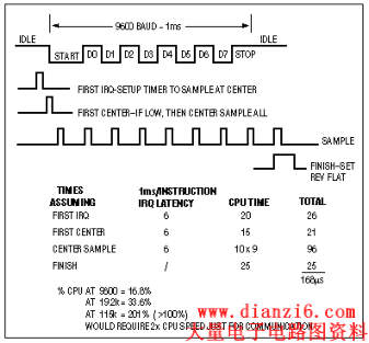
Figure 1. Software UARTs place a heavy computational load on the CPU.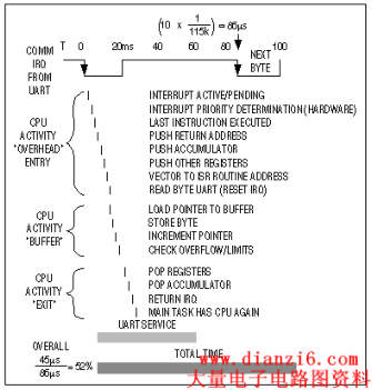
Figure 2. These details show how the CPU time is allotted in servicing a software UART.
Figure 3. The percentage of CPU time required for servicing a software UART rises sharply with the baud rate.
A software UART generally requires 200 to 500 bytes of code, depending on its sophistication and the µP's capability. This requirement makes the software-UART option unworkable for many of the smaller µCs, whose total code space might be only 500 bytes. Finally, a software UART's power drain can be significant. Wake-up time for the µC is greater than a baud period in most cases, so to be ready for possible serial traffic it must run continuously.
In contrast, a MAX3100 UART system offers numerous advantages: it implements a full handshaking interface with only four port lines. A fifth line (an interrupt line) is optional. Code size is about 50 bytes. The µP/UART combination can save a tremendous amount of power by going into sleep mode between serial-data transmissions. Finally, the MAX3100's timing requirements do not change with the baud rate. Its internal FIFO stack alleviates much of the real-time processing burden caused by the burst-mode message traffic common in small systems.
The MAX3100 UART provides an interface between the synchronous serial-data port of a µP (compatible with SPI™, QSPI™, and Microwire™ standards), and an asynchronous serial-data communications port such as RS-232, RS-485, or IrDA. For a brief description of SPI, see the sidebar to this article, "Serial Peripheral Interfaces."
The MAX3100 combines a simple UART and baud-rate generator with an SPI interface and interrupt generator. Writing to an internal register configures the UART for baud rate, data-word length, parity enable, and enable of the 8-word receive FIFO. This "write configuration" register contains four interrupt-mask bits, and it also selects between normal UART and IrDA timing.
The programmable baud-rate generator is capable of rates from 300baud to 230kbaud (Figure 4). Bits B0-B3 in the write-configuration register determine the baud-rate divisor (BRD), which divides down the frequency of the crystal between terminals X1 and X2. The MAX3100 oscillator accepts a crystal of 1.8432MHz or 3.6864MHz, and it also accepts a square wave at X1 with a 45% to 55% duty cycle.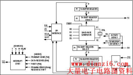
Figure 4. A new version of the venerable UART enables 8051 microcontrollers to communicate using an IrDA data link.
The transmitter section accepts SPI/Microwire data, formats and loads it into the transmitter buffer register, and shifts it in asynchronous-serial format to the TX output. Internal logic adds start and stop bits and clocks the data out at the selected baud rate. The receiver section accepts data in serial form and detects the start bit on a high-to-low transition. The center of this start bit is defined by a majority vote (minimum 2 of 3) following the 7th, 8th, and 9th samples of the internal 16x baud clock (Figure 5). An 8-word FIFO stores the received data. At the center of the first stop bit, the receiver begins searching for the next start bit.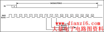
Figure 5. The MAX3100 identifies an incoming start bit if at least two of the three mid-pulse samples are low.
Opto-conditioned inputs and outputs enable the MAX3100 to receive optocoupler outputs and drive optocoupler inputs directly. That is, the UART's receiver input (RX) is a Schmitt-trigger circuit, and its transmitter output (TX) is capable of sinking 25mA. The MAX3100 also includes two general-purpose ports with opto-conditioning (active-low RTS and active-low CTS), which are useful for handshaking and control (RS-232 and RS-485 driver enable, respectively).
The MAX3100's 8-word FIFO and interrupt logic conserves CPU computing time. By allowing up to eight characters to be read each time, the CPU services a receive-activity interrupt (RA), and the FIFO buffers the CPU transfer rate from the UART's serial-data rate. The MAX3100's one interrupt input can be set by any of four sources: parity received (Pr), received data (R), receiver activity/framing error (RA/FE), and transmit buffer empty (T). Any or all sources can be masked.
As an additional feature of this SPI UART, the MAX3100 offers an IrDA timing mode suitable for communication with other serial infrared (SIR)-compatible devices, or for reducing power in opto-isolated applications (Figure 6). The MAX3100 was designed to drive opto-isolators directly, so to drive a serial-IR module like the HP HDSL-1000 the logic must be reversed. In IrDA mode, a bit period is shortened to 3/16 of a baud period (1.6µs at 115kbaud). With TX at logic low and RX at logic high, a data zero is transmitted as a negative pulse.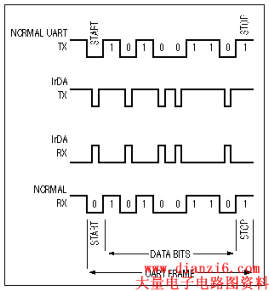
Figure 6. The narrow pulses used in IrDA communications consume less power.
In receive mode, the MAX3100 samples an RX signal halfway into a high-level transmission. This sampling occurs once, rather than three times as in the normal mode. The MAX3100 ignores pulses shorter than 1/16 (approximately) of a baud period, and the IrDA device communicating with the MAX3100 must be set to transmit pulses at 3/16 of the baud period.
The circuit of Figure 7 enables any derivative of the 8051 µC to communicate using the serial-infrared (SIR) format established by IrDA. Communication is a two-stage process in which the µC first transmits via a "bit-banged" SPI serial interface to the MAX3100 (IC1), and IC1 in turn formats the message in IrDA mode. The UART in many 8051 derivatives is not IrDA compatible, and cannot easily be made so. The circuit shown, however, provides the communication link and is easily added to an existing 8051 system with a minimum of cost, power, and software code.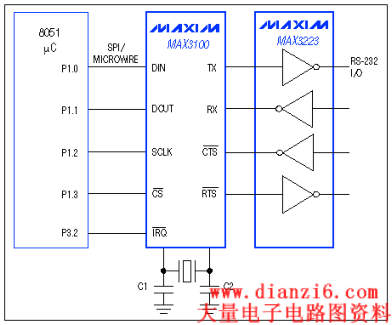
Figure 7. The MAX3100 enables IrDA communications by variants of the 8051 microcontroller.
The MAX3100 is capable of 115kbaud, but in this case the optical components shown limit the data rate to 4800 baud. The components are inexpensive, however, and most IrDA devices support data rates as low as 2400 baud. If necessary, the maximum 115kbaud is easily achieved with higher-quality optical components such as the HP-1000 IrDA module. Most IR LEDs and photodiodes are acceptable for this application, but to avoid being swamped by visible light the photodiode should include a filter. If necessary, place an external ambient-light filter in front of an unfiltered photodiode.
The operating voltage can range from 2.7V to 6V, subject to limitations imposed by the 8051. Power-supply current is about 1mA for IC1 plus 1mA per megahertz for most variants of the 8051. Timing for the SPI interface is not critical. The UART performs all real-time processing, so the processor clock can have any reasonable frequency. Unlike most system clocks, this one does not require time and temperature stability.
The MAX3100-8051 driver code is available at Maxim's website (www.maxim-ic.com). See "IrDA code for MAX3100 UART-8051" under the heading Other Software. In the MAX3100-8051 driver code the subroutine UTLK provides driver support for the MAX3100. This code translates from IrDA to RS-232 and back (for demonstration and test purposes), using the 8051's internal UART to talk on the RS-232 side. See code for details.
There are other alternatives but they carry drawbacks. One such alternative is to write a software routine for IrDA UARTs at low data rates, but the software is tricky. It uses up to 100% of the CPU's attention when active, and is impractical above 2400baud. IrDA timing can also be generated with discrete logic or a PAL, but that approach is expensive, power-hungry, and requires an external baud generator for the clock source.
The MAX3100 supports a common multidrop communication technique known as 9-bit mode (Figure 8). It uses the parity bit to indicate a message that contains a header with destination address. The MAX3100 parity mask can be set to generate interrupts for this condition. Operating a network in 9-bit mode lowers the processor overhead at all nodes by enabling the slave controllers to ignore most of the message traffic. The remote processor is then free to handle more useful tasks.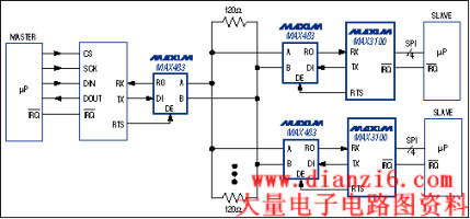
Figure 8. Nine-bit networks reduce the processing overhead in a communication network.
Nine-bit mode configures the MAX3100 for eight bits plus a parity bit, which is cleared for normal messages and set for address-type messages. Parity-interrupt masks at the MAX3100 nodes are set to generate an interrupt at high parity. The result is that standard messages are ignored because they have a cleared parity bit, and each address-type message triggers an interrupt that causes it to be captured and examined by all MAX3100s. The MAX3100 for which the message is intended processes the remainder of the message, while all others ignore it.
Because the 9th-bit parity interrupt is controlled by data in the receive register and not by data in the FIFO, it is most effective with the FIFO disabled. With the FIFO disabled, the received nonaddress words can be ignored and not even read from the UART.
In an isolated serial interface (Figure 9), the MAX3100 Schmitt-trigger inputs are driven directly by the optocoupler outputs. The optocoupler's skew does not affect timing at the asynchronous serial output, so only the SPI interface setup and hold times must be met. On the asynchronous side, you can create a bidirectional, opto-isolated interface using only two opto-isolators (one each for RX and TX). In that case, the narrow baud periods (3/16 wide) used in IrDA communications provide a power savings of 81%.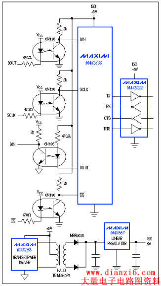
Figure 9. MAX3100 I/O pins are designed for a direct interface to optocouplers.
A separate discussion on serial peripheral interfaces begins on page 10.
As a serially accessed peripheral, the MAX3100 has the minimal number of package pins. Its synchronous-serial interface is compatible with the SPI™ and QSPI™ standards from Motorola and the Microwire™ standard from National Semiconductor. For systems in which the µC contains no hardware support, these simple interfaces can easily be implemented in a few lines of code. For the following protocol families, note that the maximum clock rates mentioned are subject to further limitation in a given application.
As a 4-wire serial interface used on COP controllers from National Semiconductor, Microwire includes clock, data-in, data-out, and chip-select lines. Its maximum clock rate is 250kHz, with a corresponding minimum "high" interval of 1µs.
Although Microwire peripherals accommodate digital words of arbitrary bit length, they usually operate on 16-bit words. Data into the device should be valid on the clock's rising edge, and data out of the device is synchronized with the clock's falling edge. Chip selects have a nonstandard, active-high polarity. Microwire Plus, which is used on National Semiconductor's HPC series of controllers, reverses the clock phase for data in and data out, and also speeds up the interface timing.
The SPI interface used on Motorola's line of controllers is very similar to National Semiconductor's Microwire. Though restricted to 8-bit-multiple digital words, it also consists of a clock line, data-in and data-out lines, and a chip-select line (see figure). The maximum clock rate is higher than that of Microwire: 1Mbps to 2Mbps (depending on the processor) for SPI, and more than 10Mbps for QSPI.
QSPI and SPI are indistinguishable to an external slave device. QSPI automates the SPI process with an automatic chip-select generator and a 16-level hardware queue internal to the controller. QSPI also gives digital control over the clocking of data in and out: a CPHA bit controls the clocking phase and a CPOL bit controls the marking polarity.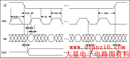
This SPI serial-interface timing is closely related to that of the QSPI and Microwire standards.
 温馨提示; 本站的资料全部免费下载,为方便下次找到本站记得将本站加入收藏夹哦,牢记网址http://www.dianzi6.com
|
此页提供New IC Caps Two Decades of UAR嵌入式系统开发,嵌入式开发, 嵌入式系统参考。本站还有更多的嵌入式系统相关资料分享。
Copyright© www.dianzi6.com Inc. All rights reserved 。 1 2 3 4 5 6 7 8 |
|