Reference Design for a Class-D, 2.1 Channel, Audio Amplifier for an MP3 Player Docking Station
Abstract: This reference design demonstrates the use of the MAX9736 Class D audio amplifier in a stereo audio, docking station application. The MAX9736 2.1 demo box is a complete powered speaker dock that uses two MAX9736 ICs to drive a 3-channel speaker system consisting of two 2in satellite speakers and one 5in subwoofer. The reference design is intended to be used with a portable audio player as its main music source. The overall solution size is very compact and features active equalization, power-supply monitoring, and dynamic equalization for the subwoofer.
Important Design Features
- Compact all-in-one design
- Operates from a single 12V to 20V DC power supply
- High SPL output from a small box
- High-efficiency Class-D design
- Active EQ, including dynamic bass equalization
- Excellent sound quality from cost-effective drivers
Bill of Materials
Designator
Qty
Description
C1
1
470µF ��20% 25V aluminum electrolytic capacitor
Panasonic® EEU-FM1E471
C2, C12, C310
3
0.1µF ��10% 50V X7R ceramic capacitor (0603)
Murata® GRM188R71H104K
TDK C1608X7R1H104K
C321
1
1µF (0603)
C16
1
10µF (1206)
C106, C109�C111, C114, C206, C209�C211, C214
10
NS (0603)
C3�C5
3
0.1µF ��10% 16V X7R ceramic capacitor (0603)
Murata GRM188R71C104K
TDK C1608X7R1C104K
C13
1
0.1µF (0603)
C316�C317
2
0.1µF (0805)
C303
1
0.33µF (0603)
C302
1
0.47µF (0603)
C305, C307
2
100nF (0603)
C103�C104, C203�C204, C301
5
100pF (0603)
C121, C220�C221, C120, C314�C315
6
100pF (0603)
C117�C119, C217�C219
6
10nF (0603)
C107, C207
2
150pF (0603)
C306, C308
2
15nF (0603)
C6�C10, C15, C313, C318�C320
10
1µF ��10% 16V X7R ceramic capacitor (0603)
Murata GRM188R71C105K
TDK C1608X7R1C105K
C312, C14, C311
3
1µF (0603)
C216, C116
2
1µF (0805)
C100�C101, C200�C201
4
2.2µF (0805)
C304
1
2.2µF (0805)
C102, C108, C112, C115, C202, C215, C300
7
33pF (0603)
C208, C212
2
33pF (0603)
C322
1
33pF (0603)
C113, C213
2
4.7nF (0603)
C105, C205
2
68nF (0603)
C11, C309
2
220µF ��20% 35V aluminum electrolytic capacitor (10mm x 12.5mm)
Panasonic EEUFM1V221
J30
1
4-pin header
HIROSE DF3A-4P
U7
1
Opto-FET (DIP6-SMT)
Fairchild™ H11F1SM
L100�C101, L200�C201, L300�C301
6
Ferrite bead (1206)
FB1
1
Ferrite bead (1206)
J3
1
6-pin header
J10, J20
2
2-pin header
HIROSE DF3A-2P
J2
1
RCA® dual jack PCB mount
D1
1
LED red (0603)
D5
1
LED blue (0603)
Q2
1
Transistor NPN (SOT23)
Fairchild MMBT3904
X1�C2
2
Connector, screw mount
R7
1
Potentiometer 100K SMT
R303
1
Potentiometer 20K SMT
J1
1
Power jack, right angle
Switchcraft® 722RA
R1
1
10k�� ��5% resistor (0805)
R110, R210
2
NS resistor (0603)
R111, R211
2
10.5k�� ��5% resistor (0603)
R100, R200
2
100�� ��5% resistor (0603)
R10
1
100k�� ��1% resistor (0603)
R106, R108, R206, R208
4
10k�� ��5% resistor (0603)
R300�C301
2
10k�� ��5% resistor (0603)
R2�C3
2
10k�� ��1% resistor (0603)
R113, R213
2
11k�� ��5% resistor (0603)
R309, R311�C312, R314
4
11k�� ��5% resistor (0603)
R306
1
12k�� ��5% resistor (0603)
R114, R214
2
137k�� ��5% resistor (0603)
R305
1
14.7k�� ��5% resistor (0603)
R112, R212
2
150�� ��5% resistor (0603)
R317
1
1k�� ��5% resistor (0603)
R107, R109, R207, R209
4
1M�� ��5% resistor (0603)
R8�C9, R315�C316
4
2.2k�� ��5% resistor (0603)
R101�C102, R201�C202
4
20k�� ��5% resistor (0603)
R5
1
220�� ��5% resistor (0603)
R310, R313
2
24.3k�� ��5% resistor (0603)
R302
1
2k�� ��5% resistor (0603)
R308
1
3.24k�� ��5% resistor (0603)
R307
1
3.3k�� ��5% resistor (0603)
R115, R215
2
30.1k�� ��5% resistor (0603)
R4
1
4.22k�� ��1% resistor (0603)
R103�C104, R203�C204
4
40k�� ��5% resistor (0603)
R304
1
7.15k�� ��5% resistor (0603)
R105, R205
2
0�� resistor (0603)
D6
1
Diode, dual, common-cathode (SOT-23-3)
Fairchild MMBD4148CC
D2�C3
2
Zener diode 4.3V, 20mA (SOT-23)
Central CMPZ5229B
SPK1, SPK2
2
2in full-range loudspeaker
Tymphany® 830970
SPK3
1
5.25in subwoofer loudspeaker
Tymphany 830945
U1
1
Maxim® MAX9736BETJ+
(7mm x 7mm, 32-pin TQFN)
U2
1
Maxim MAX9736AETJ+
(7mm x 7mm, 32-pin TQFN)
U3�C5
3
Maxim MAX4234 (TSSOP-14)
U6
1
Maxim MAX809_EUR-T (SOT-23)
Detailed Design Description
The reference design consists of a single, carefully tuned box enclosure containing all of the electronics and speaker hardware. Only an external power supply and a signal source are required to complete the system.
The design features two 2in loudspeaker drivers for the left and right channels, and a 5in loudspeaker for the subwoofer. A single MAX9736B is used in stereo mode for the left/right channels and a MAX9736A is used in mono mode for the subwoofer channel. The detailed description here is divided into two sections: electronic circuit description and speakers/physical enclosure description.
Electronic Circuit Description
The electronics of the reference design comprise two sections, the left/right and subwoofer. Each section has three stages: input, EQ, and power. See Figure 1.
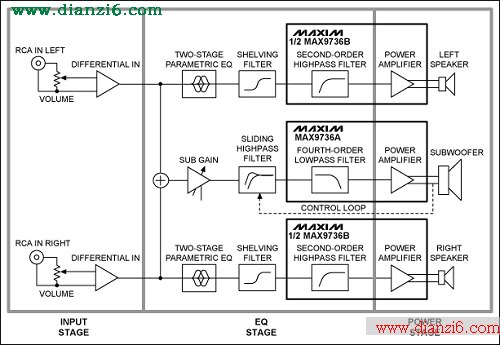
Figure 1. Electrical circuit block diagram features the MAX9736 Class D audio amplifier. The design has an input, EQ, and power stage.
Input Stage
The input stage is common to both the left/right and subwoofer sections. A stereo, log-taper potentiometer is used as a volume control to adjust the signal level to the preamplifier. To avoid ground loops, the input is sensed differentially and the RCA input connectors are not directly connected to the system ground. A 100�� resistor is used to reduce the common-mode voltage; U3-A and U3-D (see schematics below) perform differential-to-single-ended conversion with a gain of 2. The outputs of the input stage are referred to VREF, the reference voltage of power amplifier U2 which is buffered using U5-D.
EQ Stage
After the input stage, the left and right signals are passed to a two-stage parametric EQ built around U3-B (for left) and U3-C (for right). Each parametric EQ uses an op-amp gyrator to simulate an inductor in an LC-series resonant circuit. The series circuit has two access points for either attenuation or boost, and the access points are realized by two different capacitors. C105 and C106, for example, are the boost and attenuation points for the first parametric EQ band for the left channel. If only C106 is used (and C105 is not stuffed), the resonant circuit forms a voltage-divider in combination with the series resistor R105 (10k��), and the resonant frequency is attenuated. Conversely, if only C105 is used, the feedback is reduced, resulting in a boost at the resonant frequency. If neither of the capacitors is used, then the band is disabled.
The resonant frequency, f0, can be calculated using the equation:
f0 = 1/(2 �� �� �� ��(L0 �� C0))
Where:
L0 = R108 �� C107 �� R107
C0 = C105
And the Q is:
Q0 = ��(L0/(C0 �� R0²))
A third EQ band is added that realizes a shelving filter and only needs an RC: one capacitor (C113 for boost; C114 for attenuation) and one resistor (R111).
As a stereo Class D IC, the MAX9736 also features two integrated op amps at the input. Available to use for general filtering, in this reference design those op amps are used to build a second-order highpass filter for the left/right channels. The op amps have their negative inputs and outputs accessible, so a multiple-feedback inverting filter configuration is used. C116/C216 are for blocking the DC-input voltage to reduce output offset.
Power Stage
The design features three channels of speaker power amplification. A MAX9736B is configured in stereo mode to drive the left and right speakers, and can provide 2 �� 11W into 4��. For the third channel, a MAX9736A is configured as a mono subwoofer amplifier.
In mono mode, the two Class D outputs of the MAX9736A are connected in parallel to allow for higher output power. In mono mode the subwoofer channel can deliver 30W into 4�� (VDD = 19V). The input stage for the subwoofer channel is the same as that used for the left and right channels. After the input stage, the left and right signals are then summed using U5-B to create the mono subwoofer channel. R303 is used to set the subwoofer channel gain at the summing amp.
To enable a maximally flat response down to very low frequencies, the system is configured with a sixth-order filtered alignment for the subwoofer. This approach means that the fourth-order highpass response of the vented speaker is supplemented with a second-order electrical highpass in the active circuitry. U5-C is used to realize the noninverting Sallen-Key, second-order highpass filter for the subwoofer.
This system requires a high Q, which leads to 13dB of boost at 40Hz. To avoid overloading the speaker and amplifier, the Sallen-Key filter is set up to act as a sliding highpass; the filter acts dynamically as the amplifier output reaches its limit. The value of input resistor R305 is designed to reduce automatically (using the opto-coupled FET, U7) to a value so that the filter Q is lowered to 0.5, resulting in no boost at all.
The peak output voltage of the subwoofer amplifier, U2, controls the signal to the opto-FET. D6 and C16 form a peak detector, which senses the output peak level with a fast attack time. The operating threshold for the peak detector can be adjustable or fixed, depending on whether R7 is stuffed or R8/R9 are stuffed. The LED D5 turns on when this control circuit is active.
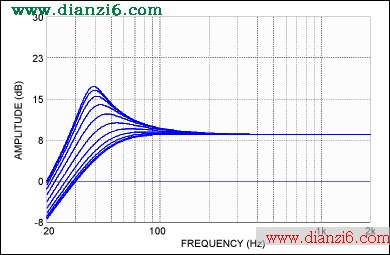
Figure 2. Simulation results of the dynamic bass boost from the subwoofer channel. The Q of the highpass filter is reduced while the cutoff frequency is also increased, as the subwoofer level approaches its limit.
The two op amps built into the MAX9736A are configured into a fourth-order lowpass subwoofer filter that complements the highpass filter used for the left/right channels.
J1 is the power-supply input connector chosen to be a standard laptop-type coaxial socket. A typical laptop power supply has an average output voltage of around 19V and serves as a good power source for the docking system. After some filtering through C1 and C2, the voltage is labelled PVDD and D1 is set to light blue when power is attached.
A simple reset circuit (through U6) is used to create a mute signal on power-up and power-down for both amplifier chips. This step avoids output transient noises due to input circuitry settling. The mute control threshold is programmed to approximately 10V with the R3 and R4 resistor-divider.
The MAX9736 features a patented filter-less modulation method which eliminates the need for bulky inductor-based filters. Only simple ferrite beads (L100 to L301) are required at the output.
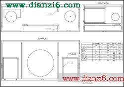
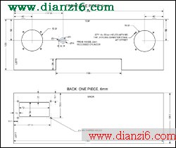
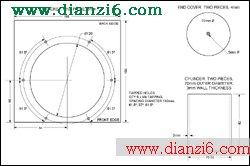
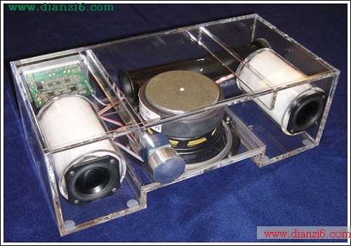
Speakers and Physical Enclosure
The loudspeaker used for the subwoofer is a 5in-diameter model from Tymphany, part 830945, with a 4�� nominal impedance and a resonance frequency of 47.4Hz. The 2in loudspeakers used for the left and right channels are model 830970, also from Tymphany. These loudspeakers have 4�� nominal impedance and a resonance frequency of 147.5Hz.
A low f3 of 35Hz is targeted for the acoustic system, so a sixth-order alignment is used. That alignment includes a second-order highpass filter within the active crossover. The overall system is housed in a single box enclosure with the three loudspeakers, tuned port, and circuit PCB. The subwoofer is mounted as down-firing to minimize the box size and to help increase efficiency by compression loading. The resulting box volume is approximately 3.79l and the vented port is tuned to 54Hz. The outside overall box dimensions are approximately 355mm x 180mm x 120mm. The speaker crossover equalization is designed as a fourth-order Linkwitz-Riley at 250Hz; the speaker equalization for the satellites consists of a parametric EQ with f = 500Hz, gain = +6dB, Q = 0.5, and a shelving filter with f3 = 3.8kHz and a gain of +5.8dB. Figure 3 shows the system's response.
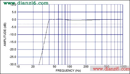
Figure 3. Total system simulated response shows maximally flat down to 40Hz.
The mechanical drawings included in this document are copies of those used to construct the prototype model. The prototype was built using 1/4in clear acrylic plastic and assembled with drilled/tapped screws and acrylic adhesive. A consumer product version might be constructed using a more cost-effective material such as wood, MDF, ABS, etc.
Circuit Schematics
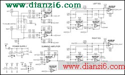
More detailed image (PDF, 80.4kB)
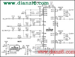
More detailed image (PDF, 84.4kB)
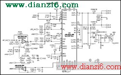
More detailed image (PDF, 92kB)
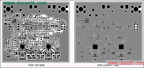
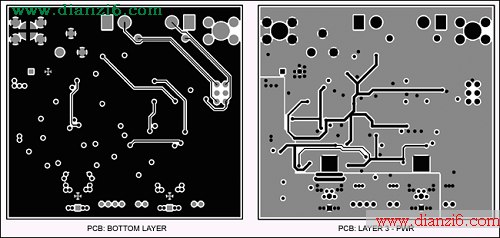
PCB Layout
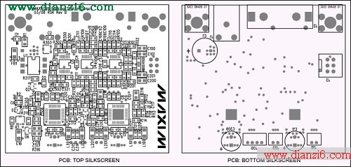
More detailed image of the Top Silkscreen (PDF, 277kB)
Mechanical Drawings
More detailed image (PDF, 72kB)
More detailed image (PDF, 56kB)
More detailed image (PDF, 52kB)
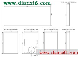
More detailed image (PDF, 48kB)
Picture of System
Fairchild is a trademark of Fairchild Semiconductor.
Maxim is a registered trademark of Maxim Integrated Products, Inc.
Murata is a registered trademark of Murata Manufacturing Co., Ltd.
Panasonic is a registered trademark of Matsushita Electric Industrial Co., Ltd.
RCA is a registered trademark of RCA Trademark Management SA Corporation France.
Switchcraft is a registered trademark of Switchcraft, Inc.
Tymphany is a registered trademark of Tymphany Corporation.
<-- END: DB HTML -->
�������
Reference Design for a Class-D, 2.1 Channel, Audio Amplifier for an MP3 Player Docking Station��ƪ���²����������Ƽ������ѷ���Ŷ��
 ��ܰ��ʾ; ��վ������ȫ��������أ�Ϊ�����´��ҵ���վ�ǵý���վ�����ղؼ�Ŷ���μ���ַhttp://www.dianzi6.com